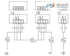
【例】绘制如图2-39所示的电缆配置图。
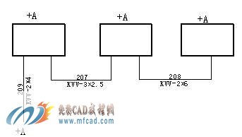
图2-39电缆配置图例
画法步骤
(1)创建新的图形文件 选择→【开始】→【程序】→【Autodesk】→【AutoCAD2008中文版】→【AutoCAD2008】进入AutoCAD2008中文版绘图主界面。
(2)绘制三个单元
选择线的宽度为0.3 ∥
 <!--[if !vml]-->
命令: _rectang ∥ 启用长方形命令
 <!--[if !vml]-->
指定第一个角点或 [倒角(C)/标高(E)/圆角(F)/厚度(T)/宽度(W)]: ∥绘图区域单击一点
指定另一个角点或 [面积(A)/尺寸(D)/旋转(R)]:
∥单击另一角点,大小自定,绘制第一个矩形
命令: _copy ∥启用复制
 <!--[if !vml]-->
选择对象: 指定对角点: 找到 1 个 ∥选择小方框
当前设置: 复制模式 = 多个
指定基点或 [位移(D)/模式(O)] <位移>: ∥小方框的右下角点
指定第二个点或 <使用第一个点作为位移>: ∥正交打开,依次进行复制
结果如图2-40所示。
图2-40画图步骤1
(4)检查图形,绘制连接线
选择线的宽度为0.18 ∥
 <!--[if !vml]-->
命令: _line 指定第一点: ∥启用直线
 <!--[if !vml]-->
指定下一点或 [放弃(U)]: ∥正交打开,按从左到右顺序依绘制
结果如图2-41所示。
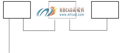
图2-41画图步骤2
(5)命令: _mtedit ∥启用多行文字
 <!--[if !vml]-->
标注文字时,字体为宋体字,大小根据图形的实际大小来确定字的高度,为了能保证字体的一致性,建议学生同样大小的字体确定一个之后,其余都进行复制,然后对复制后的文字双击进行修改,这样效率比较高。如果文字的方向不一致,可先标出一个,对其进行旋转,这样就能满足要求了。
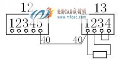
结果如图2-42所示。
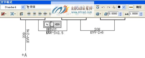
图2-42画图步骤3
【练习题】
一、绘制如图2-43所示电气电路部件图。
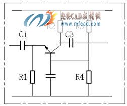
2-43电气电路部件图
二、绘制如图2-44所示起动器主电路连接线图。
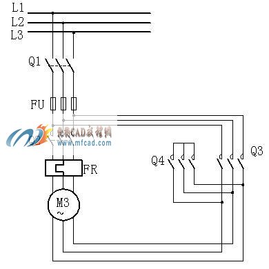
图2-44起动器主电路连接线图